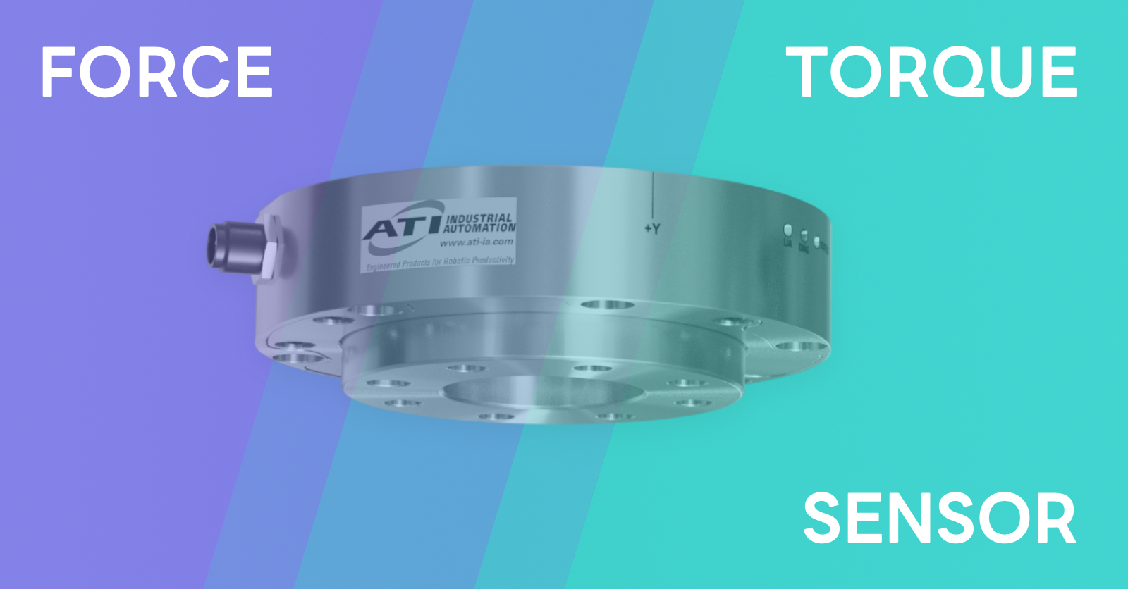
To enable the robot to feel the object it holds in its gripper, it is equipped with a sensing device – a force/torque (F/T) sensor. This sensor converts the forces acting on it – the force configuration – into a set of numerical values. There are six such values in total: force and torque components along each of the three axes of a Cartesian coordinate system. The forces acting on an object mounted on the sensor are transmitted directly to the sensor itself. This enables precise control over the mutual position and contact between objects.
We have already discussed how to connect to the sensor and retrieve force configuration data using the netft utility. Here, we will focus on creating a full-fledged industrial module for the ATI sensor, which will allow the device to be integrated as a digital twin into the IndustrialKit/RCWorkspace environment.
Model
To determine the force configuration, the ATI Multi-Axis Force/Torque Sensor model 9105-NET-OMEGA85 is used, capable of measuring all six components of force and torque. The system includes a transducer, a flexible shielded cable, and a data acquisition system with Ethernet/DeviceNet interface or an F/T controller. These sensors are used across various industries for product testing, robotic assembly, grinding, and polishing – as well as robotic surgery, tactile technologies, rehabilitation, neurology, and more.
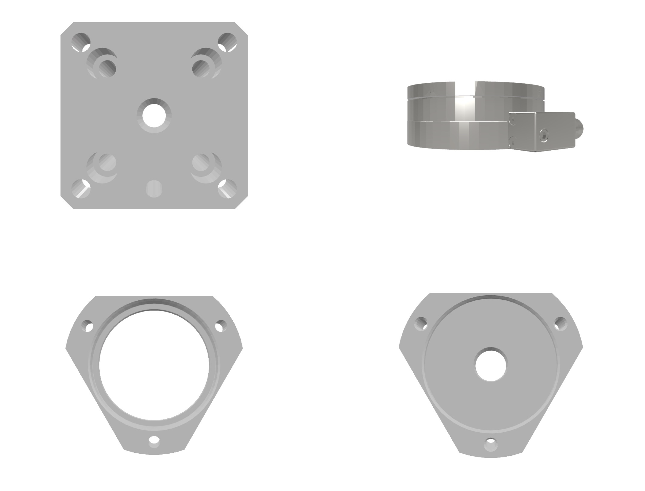
The sensor has a cylindrical measuring module with two triangular flanges, one of which is used for mounting to the robot manipulator and the gripper. Additional fastening elements were modeled in the lab based on technical drawings. The sensor dimensions are n mm (diameter) and n mm (height). ATI also provides CAD models, which are converted to STL format and added to a SceneKit (SCNScene) scene.
Code
The modified netft utility functionality is implemented as the fetch_ft_data function. It takes the IP address as a required argument (additional ones include port, command, number of samples) and returns a string of space-separated force configuration values. In case of error, it returns an empty string. This internal function is used by other connector methods — such as updating register and statistical data.
The only connection parameter for the current connector implementation is the sensor’s IP address, passed to the connect function. The F/T sensor becomes available immediately via Ethernet, but availability can only be verified by attempting to request data. If the test response is successful, the connector enters the connected state and begins syncing data with the virtual RTC device.
Module Make
The F/T sensor module is created using Industrial Builder by adding necessary resources into an STC package, combining them into a tool module, and compiling into an external file.
In the Components section, add the SCNScene with the sensor model and the listings for the Model Controller and Connector. Then, in Modules → Tool, create a new module, insert the code into the appropriate sections, and assign the only scene of the F/T sensor as the primary resource.
To compile the module, go back to the Package section, then open Process → Files. From the list, select ATI_FT_Sensor and run Build. Ensure the Compile Program Elements checkbox is enabled.
To integrate the device, link the compiled module in the RCWorkspace settings. Under Modules, specify the folder where the external module was saved. If everything was set up correctly, the app will detect existing modules and start the component servers.
Testing
The device can now be added to an RTC preset. In the Tools section, a new entry appears: External – ATI_FT_Sensor, along with its model. For the tool-sensor, statistics can be viewed as graphs and state disclosure groups.
The statistics window allows setting the scope and update period. Scope defines whether stats are collected only during actions (e.g. gripping) or throughout RTC runtime. Since the F/T sensor only returns data, we set scope to Constant. This allows real-time data updates during system operation or while a device is open in Tools/Robots.
The default update period is 0.01 seconds. Enable the Enabled toggle to see simulated force configuration data updating in real time.
Note: Data acquisition via Observer and its registration in RTC happens exactly at the moment of the request. It is not affected by statistical update parameters – they are separate systems.
Finally, let’s stream real sensor data. For testing, grip a spline shaft with a pneumatic gripper mounted on a robot along with the F/T sensor, and move it above a sponge on the setup table.
Open the connector and connect using the sensor’s IP address. Return to the statistics view. Lower the shaft and press it against the sponge. You’ll see how force and torque values change on the graph, particularly the vertical component increases significantly.
Thus, we have added a new sense to the robot – allowing it to feel the objects it holds – and demonstrated how to create a sensor tool module and integrate it into the RTC control platform.
